Q : please explain pcb layout. (pcb 레이아웃을 설명해주세요.)
A :
Sure, I'd be happy to explain PCB layout.
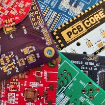
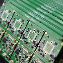
PCB layout refers to the process of designing the physical layout of a printed circuit board (PCB), which is used to connect electronic components in a device. The layout involves arranging the components and the conductive traces that connect them in a way that is efficient and effective for the intended function of the device.
The process typically involves using software tools to create a virtual representation of the PCB and its components. The designer will typically start by placing the components in the desired locations, based on the requirements of the circuit design. The software will then generate the necessary connections between the components using copper traces, which are usually laid out on multiple layers of the PCB.
The layout process can be complex, as there are many factors to consider, including the electrical characteristics of the components, the physical constraints of the device, and the manufacturing process that will be used to produce the PCB. The designer will need to take into account factors such as the spacing between the traces and the thickness of the copper layers, to ensure that the board meets the required electrical and mechanical specifications.
Once the layout is complete, the design files are typically sent to a manufacturer who will produce the PCB. The manufacturing process involves creating a physical board from the design files, which typically involves using a combination of etching, drilling, and other techniques to create the necessary features on the board.
Overall, the PCB layout process is an important step in the development of electronic devices, as it enables the efficient and effective connection of electronic components.
질문을 하니 이렇게 답을 해주었다.
구글번역으로 번역해 봤다.
구글번역:
물론입니다. PCB 레이아웃에 대해 설명해 드리겠습니다.
PCB 레이아웃은 장치의 전자 부품을 연결하는 데 사용되는 인쇄 회로 기판(PCB)의 물리적 레이아웃을 설계하는 프로세스를 말합니다. 레이아웃에는 장치의 의도된 기능에 대해 효율적이고 효과적인 방식으로 구성 요소 및 구성 요소를 연결하는 전도성 트레이스를 배열하는 작업이 포함됩니다.
이 프로세스에는 일반적으로 소프트웨어 도구를 사용하여 PCB 및 구성 요소의 가상 표현을 생성하는 작업이 포함됩니다. 설계자는 일반적으로 회로 설계의 요구 사항에 따라 원하는 위치에 구성 요소를 배치하는 것으로 시작합니다. 그런 다음 소프트웨어는 일반적으로 PCB의 여러 레이어에 배치되는 구리 트레이스를 사용하여 구성 요소 간에 필요한 연결을 생성합니다.
부품의 전기적 특성, 장치의 물리적 제약, PCB 생산에 사용될 제조 공정 등 고려해야 할 요소가 많기 때문에 레이아웃 공정이 복잡할 수 있습니다. 설계자는 기판이 필요한 전기적 및 기계적 사양을 충족하는지 확인하기 위해 트레이스 사이의 간격과 구리 레이어의 두께와 같은 요소를 고려해야 합니다.
레이아웃이 완료되면 설계 파일은 일반적으로 PCB를 생산할 제조업체로 전송됩니다. 제조 프로세스에는 설계 파일에서 물리적 보드를 생성하는 작업이 포함되며 일반적으로 보드에 필요한 기능을 생성하기 위해 에칭, 드릴링 및 기타 기술을 조합하여 사용합니다.
전반적으로 PCB 레이아웃 프로세스는 전자 부품의 효율적이고 효과적인 연결을 가능하게 하므로 전자 장치 개발에서 중요한 단계입니다.
.
.
AI의 답변이 놀랍다..
.
.
두려워하지 말라 내가 너와 함께 함이라
놀라지 말라 나는 네 하나님이 됨이라
내가 너를 굳세게 하리라
참으로 너를 도와 주리라
참으로 나의 의로운 오른손으로 너를 붙들리라
'PCB 설계 > PCB설계-관련 정보' 카테고리의 다른 글
| KiCad 회로도 핀 수 세는 프로그램 (0) | 2024.12.24 |
|---|---|
| Differential Pair 신호선에서 _t, _c 뜻 (0) | 2024.05.31 |
| PCB 배선 저항 계산 공식, 전압강하 계산 공식 (0) | 2023.02.27 |
| OrCAD to KiCad netlist converter (11) | 2022.10.19 |
| PCB 설계 할 때 가장 중요한 것? (2) | 2022.09.27 |

